Drilling platform and casings

Special Process Well Drilling Technology: A Comprehensive Guide

To address complex geological conditions and special well type requirements, we provide professional special process well drilling solutions, covering directional wells, horizontal wells, extended reach wells, and multilateral wells. By leveraging advanced tools, customized solutions, and proven technologies, we help clients effectively overcome drilling challenges, enhance operational efficiency, mitigate risks, and ensure safe and efficient well completion.

Special process wells refer to all non-conventional wells (excluding vertical wells) in oilfield development. This industry-specific term includes: directional wells, horizontal wells, sidetracking wells, extended reach wells, multilateral wells, etc. Advanced drilling control technologies for special process wells help increase single-well production, improve economic recovery rates, and enhance overall oilfield development efficiency.

Directional Well Drilling Technology

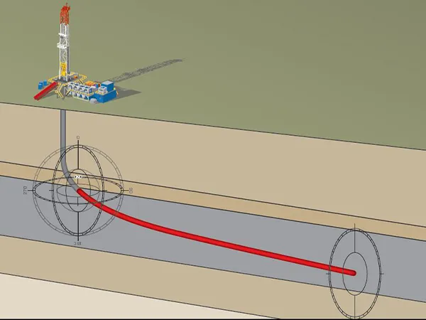
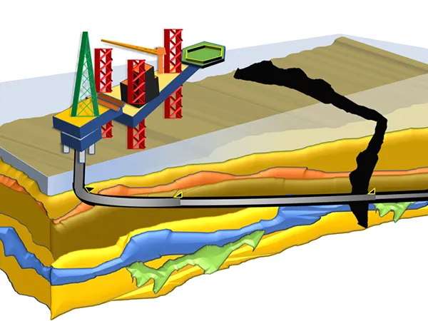
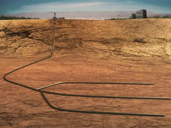
A directional well is a technical drilling term referring to a wellbore drilled along a pre-designed trajectory with controlled inclination and azimuth changes.

The primary objective of directional well design is to achieve the intended drilling purpose. This serves as the main basis and fundamental principle of directional well design. Designers must optimize the well profile, trajectory type, casing program, drilling fluid selection, and completion method based on specific drilling objectives to ensure safe, efficient, and high-quality drilling operations.

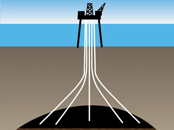
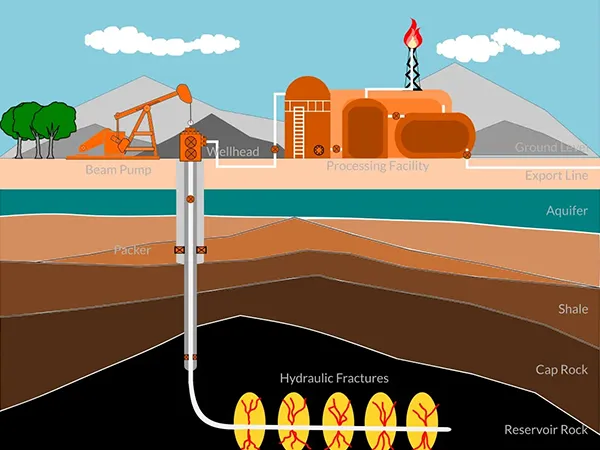
Applications include cluster drilling on artificial islands, directional wells drilling from onshore to offshore, fault-controlled trajectory drilling, drilling in areas where surface conditions (such as mountains or buildings) restrict access, subsurface trap exploitation, directional relief well engineering, deviation correction or sidetracking operations, multi-lateral target wells, and horizontal well development.

Directional well schematic diagram

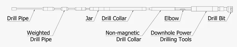
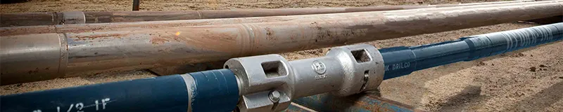
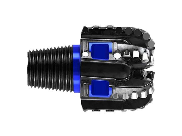
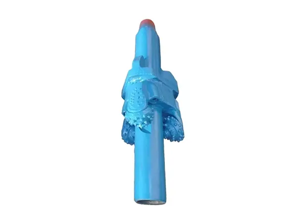
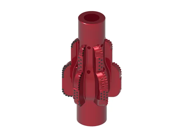
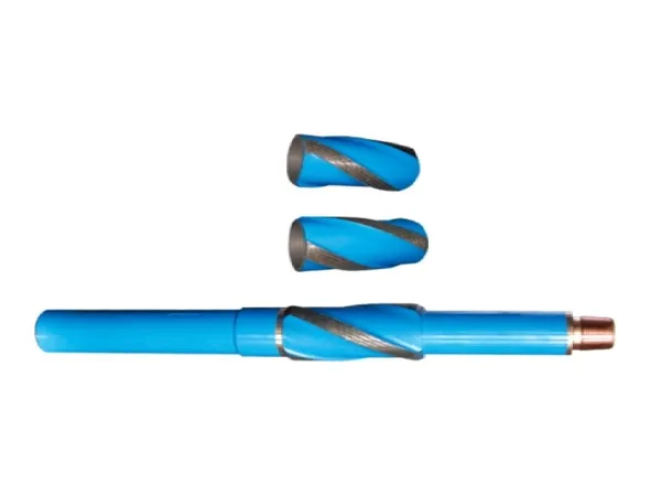
Drill string assemblies for directional wells are generally classified by their function into hold-angle assemblies, drop-angle assemblies, building-angle assemblies, micro-building assemblies, deflection tools, and steering systems. For each well section, appropriate BHA configurations and drilling parameters must be selected based on the planned well profile. This ensures the drilled hole follows the designed trajectory – the fundamental principle of directional well path control. When designing a directional well BHA, the principle of stiffness compatibility must be observed; that is, the stiffness of the entire drill string should gradually decrease and not increase, to avoid stiffness incompatibility that could prevent the drill string from being run in.

Schematic diagram of directional deflection bottom hole assembly
Cluster Well Drilling Technology

Cluster wells refer to multiple wells (ranging from several to over a hundred) drilled from a single well pad or platform. While the surface wellheads are spaced just meters apart, each wellbore extends in different directions underground.

Cluster drilling is typically employed due to surface constraints (such as limited land resources or harsh surface conditions), regional factors (such as extremely cold, frozen areas, or tidal flats), and economic considerations (as it offers higher technical and economic benefits compared to single-well drilling). Cluster well drilling can reduce costs associated with equipment relocation, road construction, pipeline installation, and communication setup. It also simplifies the oil and gas extraction process and helps protect the environment. Due to these advantages, cluster wells are widely used in offshore drilling platforms, shallow water artificial islands, tidal flats, and the development of heavy oil and high pour point oil reservoirs.

Cluster well schematic diagram

Key construction steps for cluster wells: Due to the small wellhead spacing in cluster well drilling, the vertical section before kickoff (typically 500–1200 m) requires exceptionally high precision drilling quality. To ensure the quality of the vertical section, a critical technical step is collision avoidance. The commonly employed anti-collision method involves utilizing visualization technology to track and monitor the wellbore trajectory. Visualization leverages computer displays to intuitively observe the spatial configuration of the wellbore trajectory from various three-dimensional perspectives. This technology has been widely adopted in petroleum exploration and development. It offers substantial value in anti-collision for adjacent wells, relief wells, and directional wells, as well as in the monitoring and control of target entry and wellbore trajectory, and in the quality assessment of actual drilling trajectories. At present, the most commonly used methods include horizontal distance scanning, minimum distance scanning, and normal distance scanning.

Horizontal Well Drilling Technology

A horizontal well is a specialized well type with maximum inclination reaching or approaching 90° (generally no less than 86°), maintaining a designated lateral section within the target formation.

Horizontal wells demonstrate broad applicability across reservoir types, featuring "fewer wells with higher production" characteristics. They are primarily deployed in geologically confirmed reservoirs to enhance productivity in low-permeability reservoirs, reduce water coning from edge/top/bottom aquifers, delay water breakthrough and control water cut, and maximize penetration through vertical fracture networks in heterogeneous reservoirs. Additionally, they can access multiple hydrocarbon-bearing zones in multilayered reservoirs and improve ultimate recovery rates.

Horizontal well schematic diagram

The design and implementation of horizontal wells must satisfy the requirements of exploration, development, and oil production, with the objective of enhancing the overall efficiency of exploration and development operations. Currently, drilling methods are primarily categorized by steering tools into slide-steering drilling and rotary-steering drilling. Based on the guidance approach, they can be classified as geometric steering drilling and geosteering drilling.

Selecting an appropriate bottom hole assembly (BHA) is fundamental for precise trajectory control in horizontal well drilling. Proper selection and use of the BHA not only improves trajectory control accuracy and drilling speed but also helps achieve a smooth wellbore with uniform curvature and minimal dogleg severity.

For high-angle and horizontal sections, an inverted BHA configuration is recommended, placing drill collars and heavy weight drill pipe in the low-angle or vertical sections to apply weight on bit while preventing buckling of regular drill pipe during drilling. The length of the slant drill pipe should be equal to or greater than the total length of the wellbore below the 45° inclination and the planned drilled section.

To better handle complex downhole conditions and potential incidents in high-angle and horizontal intervals, a drilling jar can be placed at an appropriate downhole position.

Surface-deployed drilling jar

The drill bit selection must be based on the formation type, and the selected drill bit should have good gauge-holding performance. If a roller cone drill bit is selected, it should have characteristics and performance suitable for high rotation speeds to match downhole motor drilling. When hard alloy inserts are welded onto a roller cone drill bit, in addition to preventing outer diameter wear, their effect on reducing the drill bit’s anisotropy should also be considered. Shortening the gauge length of a PDC drill bit enhances steerability, while increasing the gauge length helps maintain the well inclination. During rotary drilling in hold-angle or horizontal sections, while the drill bit selection range is relatively wide, directional control capability must be carefully considered.

PDC drill bit on a white background
Extended Reach Wells (ERD)

An extended reach well generally refers to a directional well where the ratio of horizontal displacement to vertical depth is equal to or greater than 2. Some definitions also consider the ratio of measured depth to vertical depth.

Extended reach wells are characterized by long horizontal displacements and extended tangent sections with high inclination angles. This feature accentuates gravitational effects, leading to two significant challenges in ERW drilling: increased difficulty and workload in wellbore trajectory measurement and control, and elevated friction and torque between the downhole drill string and the wellbore wall. A well-designed well trajectory is one of the key factors to the success of extended reach wells. It directly impacts drilling equipment capabilities, wellbore control, wellbore cleaning, safe drilling, casing running, and downhole operations.

Extended reach well schematic diagram
Selection of Drilling Equipment:
Drive System

Drilling extended reach wells imposes higher demands on the drive system. Considering both drilling efficiency and downhole safety, a top drive system is essential. The torque output of the top drive must match the torsional strength of the smallest drill pipe thread used, typically providing 61–81 kN·m of torque. For ultra extended reach wells, the torque capacity of the top drive becomes even more critical due to the increased torque challenges in long, high-angle sections.

Circulation System

To meet hydraulic requirements and ensure effective hole cleaning, the rig’s circulation system must be capable of meeting drilling demands. This may involve increasing the number of mud pumps to three or more, raising the rated power from 1600 kW to 2000 kW or 2200 kW, and boosting the rated pressure of both the mud pumps and surface drilling fluid system from 35 MPa to 42 MPa or 52 MPa.

Hoisting System

Due to the heavy lifting loads in extended reach wells, a high-capacity hoisting system is required. A powerful hoisting system not only ensures smooth tripping of drill strings but also enhances tripping efficiency and improves the ability to handle downhole complications. Currently, gear-driven drawworks with power ratings of 4000–5000 hp (2942–3678 kW) are available.

Multilateral Well Drilling Technology

A multilateral well refers to a well where two or more wellbores are drilled from a single main wellbore into the reservoir, with each wellbore completed separately. Multilateral well drilling technology is regarded as an effective method to enhance the recovery of remaining oil reservoirs, further increase single-well production, and improve the economic efficiency of field development.

The application of multilateral wells is extensive, suitable not only for sidetracking and revitalizing old wells but also for new well development, and can be applied to various types of reservoirs.

Developed from directional and horizontal drilling technologies, multilateral wells present significantly higher operational challenges and risks compared to conventional directional or horizontal wells. The primary difference lies in the complexity of the wellbore structure, as multilateral wells feature multiple junctions where branch wellbores connect to the main borehole.

Multilateral well schematic diagram
Sidetracking Well Drilling Technology

Originally an auxiliary process in drilling technology, sidetracking has long been employed in drilling operations. The application of sidetracking technology – transforming old wells into new ones, and further into complex well types such as sidetracked horizontal wells and multilateral wells for well pattern optimization, reserves enhancement, and production increase – emerged during the mid-to-late stages of oilfield development, driven by the need to repair and modify numerous aging wells. Sidetracking operations include sidetracked wellbore trajectory control and casing window cutting.

Sidetracking well schematic diagram

In the directional kickoff section, measurement while drilling (MWD) must be employed for trajectory monitoring. During rotary drilling, multi-shot surveys are typically used for trajectory measurement. If the inclination exceeds 3° in the directional section, MWD tools can be directly applied for "tool face high-side" orientation drilling. If the inclination is below 3°, MWD cannot be used immediately; instead, drilling 20–30 m beyond magnetic interference is required before switching to wireline steering tools.

The most critical phase in sidetrack drilling is casing window cutting, which is achieved through two primary methods:

Schematic diagram of Whipstock Window cutting
Whipstock Window Cutting

This method involves installing a whipstock at the predetermined depth and orientation within the existing casing. The whipstock deflects the drill bit to mill through the casing wall, creating an exit window for sidetracking operations. This technique maintains the original casing integrity without severing the tubular string.

Schematic diagram of casing section milling
Casing Section Milling

This process completely removes a specified casing segment at the target depth, exposing the formation to establish a sidetracking window. This creates a window that allows the wellbore to be sidetracked outward from the original wellbore.

Reaming technology for extending the production life of sidetracked wells: Although sidetracked wells are cost-effective and deliver rapid results, their production lifespan is relatively short. This is particularly evident in thermal recovery sidetracked wells, some of which have a production life less than half that of newly drilled wells, or even lower. Enhancing the production lifespan of sidetracked wells is a critical aspect of sidetracking technology application. The primary factors affecting the production life of sidetracked wells include limited annular clearance, non-centralized casing, and poor cementing quality. The main approach to addressing limited annular clearance is the application of reaming technology. Common reaming tools include double center reaming drill bits, eccentric reaming tools, hydraulic roller reaming tool, and hydraulically-actuated PDC reamers with mechanical positioning.

Double center reaming drill bit on a white background

Double center reaming drill bit

Eccentric reaming tool on a black background

Eccentric reaming tool

Hydraulic roller reaming tool on a white background

Hydraulic roller reaming tool

PDC type hole expansion tool on a white background

PDC type hole expansion tool

Specialized Tools

Specialized tools for complex well applications include directional subs, non-magnetic drill collars, variable diameter stabilizers, etc.

Cross-sectional view of a bent directional sub on a white background
Directional Sub

The directional sub is a specialized downhole tool used in directional drilling for wellbore deviation and azimuth correction. Two primary types include straight directional subs and bent directional subs.

Non-magnetic drill collar on a white background
Non-Magnetic Drill Collar

The non-magnetic drill collar provides a measurement environment for magnetic survey instruments that is unaffected by magnetic fields. It should be positioned close to the drill bit or near the bottom hole drilling assembly.

Variable diameter stabilizer on a white background
Variable Diameter Stabilizer

The variable diameter stabilizer adjusts its outer diameter through specific control methods, thereby modifying the mechanical characteristics of the bottom hole assembly (BHA) and enabling adjustment of the well deviation angle without tripping.